Although the power of a vacuum was first witnessed over 350 years ago, vacuum chuck technology is often overlooked in the manufacturing community. In this tutorial we’ll cover some basic limitations and to see if vacuum chuck workholding is right for your application.
To Vac or Not to Vac
In a machining environment a vise should always be the first choice in workholding due to the high mechanical clamping force. However, using a vise is not always an option for certain materials and shapes. Some soft or thin materials can be damaged or bowed by a vise. Using a vacuum chuck also allows machining of 5 out of 6 full sides of a part – vises allow limited exposure of 3 sides. If using a vise causes any of these problems, then a vacuum chuck is absolutely an ideal workholding device. The rule of thumb in evaluating if vacuum chuck workholding is right for you is best remembered by the phrase “Short and Fat”.
Evaluating the Workpiece
“Short and Fat” conveys two ideas. First, parts are best held when a large surface area (fat) is presented to the chuck surface. A high vacuum is defined as 26″ – 30″ Hg and produces a holding force of 13 – 15 PSI. For example, a 5″ x 5″ part being held by a vacuum chuck at 28″ Hg (or 14 PSI) has 350 lbs of downward holding force applied to it (5″ x 5″ = 25 sq in. 25 sq in x 14 PSI = 350 PSI). The more surface area a part has, the stronger the hold, the more aggressively material can be removed.
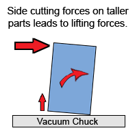
 Vises have a theoretically infinite amount of pressure that can be applied to a workpiece whereas vacuum chucks rely on the atmospheric air pressure around us to press a workpiece downward against the chuck surface. Since this force has a limit of 14 pounds per square inch (14 PSI), any forces that might lift the part should be avoided. Rather, material removal should be focused on creating sideways forces, but sideways forces on tall parts can lead to unwanted lifting due to leverage. Short parts do not experience this unwanted leverage.
How tall is too tall? Plugging in a 25:1 ratio into a simple equation offers a good starting point. Divide a part’s surface area by 25 to find a safe part thickness (5″ x 5″ = 25 sq in. 25 sq in / 25 = 1″ tall part). Many other factors play into this equation such as material type, cutter style, feed rate, aggressiveness of cut, etc. so fine tuning to the exact application is encouraged.
“Short and Fat” reminds us of the ideal part shape, but trying to keep a part in place while cutting on it is a discussion for another tutorial.
